Friday, March 30, 2012

Experiment 9

Experiment #9
Concave and Convex Mirrors

Purpose
The purpose of this lab is to observe the images produced by convex and concave mirrors; to analyze the geometry behind reflected rays on the two mirrors, how each mirror magnifies in a certain way (and sometimes flips upside down); to understand the relationship between the two mirror's different curvatures, focus points, and how they would affect the object's image to appear having different height and at different distance.

Questions / guidelines


I. Convex Mirror

1. Place an object in front of the convex mirror.
A. The image appears smaller than the actual size of object.
B. The image is upright.
C. The image is located farther relative to the position of the mirror and object.

2. Move the object closer.
The object grows in size / appears bigger as it gets closer. It also appears to more bent/ curved.

3. Move object further.
The object grows smaller and less bent.


Diagram of Convex Mirror


II. Concave Mirror
1. Place an object in front of mirror


A. The image appears larger than the object.
B. The image appears inverted when it's located behind (away) from the curvature point. When the object is close, the image would appear upright.
C. The image appears to be located relatively closer than actual distance of the object and mirror.


Object appears inverted

2. Move the object close.
The image grows larger in height (size), inverted. When it's close enough, the image would blur and when it's even closer, it would appear upright and magnified.

3. Move the object further.
If the object started off very close, it would appear upright and magnified; as the object is brought away, it would become smaller, then it would blur, then it would appear inverted and smaller. If the object started off not too close, it would start off appearing inverted. As it is brought away, it would grow less in size.


Concave mirror diagram


The graph at the end of Lab 9. d_0 = 10.5 +/- 0.1 cm, d_i = 3.2 +/- 0.1 cm, h_0 = 2.2 +/- 0.1 cm, h_i = 0.7 cm.

M = 0.3 +/- 0.2

Error Analysis


The magnification can be represented as

m = y' / y = - (s' / s)

whereas y' is the height of the image, and y is the height of object (actual). The s' are distances, just like height. m simply gives the ratio of y' and y and actual vs appearance distance.
The main source of error is due to the magnification of the ruler used when measuring the distance; while measuring the distance of object can be done easily by simply using a ruler, measuring the distance of image cannot be done by simply using a ruler; the ruler in the mirror is an image, a distorted image. An image of 1 cm is not 1 cm in real world.
To fix it, a detailed photograph/  still image should have been taken, and a comparison between the actual vs appearance distance can be made then by measuring the difference of distances (actual and image) from the photograph.


END.


Um, smile...? ;)

Experiment 5

Experiment 5
Introduction to Sound


The purpose of this experiment was to further analyze the function and shape of waves (sound waves) using human speech.

This lab used a LoggerPro software, complemented by a microphone.


Procedure:

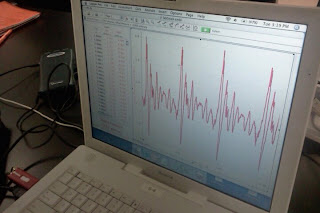
An arbitrary person would start by saying "AAAAA" to the microphone to be recorded and analyzed by loggerpro. The recording time would not exceed 2-3 seconds (1 second would suffice to determine the Frequency). Loggerpro would then show the graphical representation of such sound waves.


Questions:
1.
a. Would this be a periodic wave? Support answer with characteristics.
Yes. It shows a repeated pattern - hence the word periodic

b. How many waves are shown?
Four. There are four distinct wave crests.

c. Relate how long the probe collected data to something in everyday experience (?)
It would be analogous to having a 1-second-long speech.

d. What is the period of these waves?
t_0 = 0 s,
t_f = 0.03s +/- 0.005

Δt = 0.03s +/- 0.005
Since there are 4 waves, period, T, is 0.03s / 4 waves = 0.0073 s. One wave takes 0.0073 s to complete.

e. What is the frequency?
f = T-1
f = 133.3 waves / s

f. Calculate wavelength, assuming speed of sound to be 340 m/s
λf = v
λ = v/f, whereas v = 340;
λ = 2.57 m

g. What is the amplitude of these waves?
Arbitrary. There are no specific designated comparison for the amplitude upon recording the sound. The "height" / amplitude shown has no designated quantity unit.

h. What would be different about the graph if the sample were 10 times as long?
It depends on the time. If there were 10 waves instead of 4 in 0.03 s, then the Period would decrease, frequency would increase, and wavelength would decrease. If the time changes proportionally, then there would not be any difference. The former could happen usually when someone else speaks differently to the mic. Do wavelength vary depending on how it's being spoken?

2. Have someone else to say "AAAAA..." Compare.
There were 3.75 +/- 0.25 waves in 0.03s +/- 0.005. Less wave than previous person's data. 
T = 0.008 s/ wave
f = 125 waves
λ = 2.72 m


3. Collect data from the tuning fork. Compare it with the one made by human voice:

fork vs man:

 Fork

VS

Man

4. If the same tuning fork was used to collect data for a sound that is not as loud, what would be different from the graph?
The amplitude would vary depending on the sound "loudness" / intensity. 


Error Analysis:

There is no significant error analysis in this lab. The only possible error for this lab was the sound recording; an ideal mic would capture the sound wave function perfectly, whereas real mic would be somewhat imperfect. The graphs then, is not the entire wave function. There must have been bits missing. There is no way (at least with the present equipment) to find out the "actual" sound wave function graph, unless a "better"/ perfect, idealized mic was used, which was not possible.


Thursday, March 22, 2012

The M-in-M experiment (Marshmallow in Microwave)

Lab x
Marshmallows, Photons, and Waves

The purpose of this lab is to realize Microwave Oven as a wave-generator producing standing waves, to analyze the characteristics of such wave, and how it generates certain "hot spots" when heating foods.
The second purpose of this lab is to realize that Marshmallow absorbs heat/ energy very easily (swells rapidly within seconds), thus during a nuclear warfare, wearing a marshmallow suit is highly not recommended.
The dimensions of microwaves are L : W : H = (0.36 m : 0.36 m * 0.23 m) +/- 0.001
This blog will answer few questions on a given handout, and they are listed and answered as follows:
1. Determine the frequency of the microwaves
v = λf
length, 12cm +/- 1 (0.12 m +/- 0.0012), is half λ
f = v/λ, whereas v is speed of light (3*10^8)
f = 1.25 GHz +/- 0.0012


2. Deduce the range of possible dimensions including the smallest possible microwaves


The possible dimensions would be the wavelength of the standing wave. It is 12 cm +/- 1. Assuming the microwave is emitting perfectly horizontal wave from side to side, the smallest dimension of microwave therefore is 12 cm by 12 cm by any reasonable height.


- During the experiment, a cup of 100.0 g of water is heated for 30 s, then measured the temperature difference.
Initial temp = 20.0 +/- 0.1 C, final temp = 57.5 +/- 0.1 C. ΔT is 37.5 C. +/- 0.2


3. Total energy content of water?


Energy, or heat, is expressed in Q = m c ΔT. Where c = 4.186 J/g C
Q then, is 100g * 4.186 * 37.5 = 15697.5 J +/- 0.3


*Power, P, is joules per second. The time is 30 s, therefore Power = Q/t = 523.3 W +/- 0.3


4. How many photons per second?
Energy per Photon is expressed in E = h f
frequency is 1.25 GHz +/- 0.0012, while h is planck's constant, which is 6.626068 × 10⁻³⁴ m2 kg / s


E(per photon) = h f = 6.63 * 10^-34 * 1.25 *10^9 = 8.23 * 10^(-25) J

E(total) = 15697.5 J. +/- 0.0012
# of Photon then, is E(total) / E(per photon) = 1.91*10^28 photons. +/- 0.0012

5. What pressure do these photons exert on the side of the microwaves?

I = P/A
Area of Microwaves is W * L (it's a relatively square microwave) 0.1296 m^2 +/- 0.002
Power is calculated to be 523.3 W +/- 0.3
I = 4037.8 W/m^2 +/- 0.302

p(rad), radial pressure, is I / c;
p = 1.35 * 10^(-5) N/m^2 +/- 0.302


END

Expiration date : 12/ 08/ 2008

Friday, March 16, 2012

Experiment 4

Lab 4
Standing Waves

The purpose of this lab is to observe and understand the relationship between a standing wave's Force, amount of harmonic motions, applied frequency, its velocity, and wavelength altogether in one big picture.
The equipment used in this lab were:
A wave generator, various hanging mass, a string with relatively uniform μ, pulley, meter stick.

The setup is as follows:

First, the string will be extended across a flat surface.


One end is tied onto a fixed rod; a pulley will be placed with the string running through it. 
Tied to the pulley-end is a hanging mass that serves as external force. The wave generator is setup under the vicinity of one end of the string which is tied onto a fixed surface. 
The wave generator will be set on a certain frequency until a fundamental loop is achieved (2 nodes and 1 anti-node). Such frequency will be recorded. 
The frequency will be gradually increased until the number of nodes and antinodes increased by exactly one, then the frequency will be recorded; this will be repeated until the frequency reaches no longer than 100 Hz. 


Standing wave can be expressed in a simplified form of

y(x,t) = 2A (sin (kx)) cos (ωt)


Nodes will occur whenever sin (kx) = 0, or when kx is multiples of 0, π, 2π... (kx = nπ), with n integers.
k is 2π/λ. x is the actual length of string. Therefore, 
λ = 2L / n
Using v = f λ, 
f = v n/2L

Observations and Data:
There are 2 parts of this experiments. The difference between the two are the mass of hanging mass and length of string used.
(The steps of measured uncertainty is measured on the last part of this blog)
Mass string = 3.08 * 10^-3 kg +/- 0.000005  
Length string = 2.00 m +/- 0.005
μ = mass / length = 1.18*10^-3 kg / m +/- 3.42 * 10^-4

First Part
Mass of object ~ 0.200 kg +/- 0.0005 
Length of string used (length of string within two rigid exposures) : 1.40 +/- 0.005 m
Second Part
Mass of object~ 0.050 kg +/- 0.0005
Length of exposed string: 1.87 m +/- 0.005 


Analysis (questions)
a. Find λ and value of n:

The harmonics of Part 1 looks like the picture below:
There are 6 experiments. They will be called, respectively, experiment 1-6. 
Value of λ and n for:
Experiment 1 = 2.80 m +/- 0.005, n = 1
Experiment 2 = 1.40 m +/- 0.005, n = 2
Experiment 3 = 0.93 m +/- 0.005, n = 3
Experiment 4 = 0.70 m +/- 0.005, n = 4
Experiment 5 = 0.56 m +/- 0.005, n = 5
Experiment 6 = 0.47 m +/- 0.005, n = 6

Part 2 is shown below:
There are 7 experiments. Part 2 did not start from fundamental, but 4 nodes. The values are:
Experiment 1 = 1.25 m +/- 0.005, n = 3
Experiment 2 = 0.94 m +/- 0.005, n = 4
Experiment 3 = 0.75 m +/- 0.005, n = 5
Experiment 4 = 0.62 m +/- 0.005, n = 6
Experiment 5 = 0.53 m +/- 0.005, n = 7
Experiment 6 = 0.47 m +/- 0.005, n = 8
Experiment 7 = 0.42 m +/- 0.005, n = 9

b. Plot f vs 1/λ and compare the slope with theoretical v = (T / μ)^(0.5)
x axis = 1/λ
y axis = frequency
(Slope is velocity)
Part 1 
Slope = 39.6 (m/s)
Tension = Force of gravity; 
Tension = 2 N
v = (T / μ) ^ (0.5)
v = 42.2 m/s
Δv = 2.6 m/s (6.6% difference - insignificant)


c. Repeat above for part 2 of experiment

Part 2
Slope = 22.2 (m/s)

While v = (T / μ) ^ (0.5) = 21.0 m/s
Δv = 1.2 m/s (5.4% difference - insignificant)

d. Ratios? Case 2's wave speed is approximately half of the case 1's. 
The calculated wave speed is obtained by measuring the squareroot of tension over mu. This implies that v^2 is proportional to tension (mu is constant and can be neglected). The mass difference is in the multiples of 4 (case 1 uses 200g mass whilst case 2 50g, 4 times difference). 
It is proportional, since 4 is a square of 2, and their speed is different by multiples of 2.

e. Are measured f squal to nf_1, whereas n is number of harmonics?
It is f_1. The first trial in case 1, the fundamental motion (with only 2 nodes and 1 anti-node), by using 
f_n = nf_1
and
f_1 = v/2L,
if n is 1, then
f_n = f_1, 
whilst
v/2L will return a value of 16.5.
n=1 then, implies that it is a fundamental harmonic motion.

f. Ratio of frequency of the second harmonic for case 1 compared to case 2?
In the first case, the frequencies increase by roughly  16 Hz.
In the second case, they are increasing by, roughly, 5 Hz, throughout all harmonics.


Error calculations:
Uncertainties can be expressed as
((∂F/ ∂x * uX)^2 + (∂F / ∂y * uY)^2...)^(1/2) 

Whereas m = mass and L = length,
μ (m, L) = m/L
μ/∂m = 1/L * um = 3.57*10^-6
μ/∂L  = ln(L) * m * uL = 3.46 * 10^-4
uμ then, is 3.42 * 10^-4
μ then, is 1.18 * 10^-3 kg / m +/- 3.42 * 10^-4

Possible cause of errors and other observations:
During the lab, we realized that a the string had to be relatively long in order for (any) harmonics to occur. Our very first experiment (preceding the ones listed above) had an L value of 1.1 m, and we were almost unable to get a steady fundamental nodes.
An inevitable, major source of error is, as we noticed, that the "taut and rigid" surface which one end of string is tied on is not really absolutely taut and rigid. In fact, it wiggled and shook rather violently throughout the entire experiments. We exhausted all methods trying to eliminate/ damp the unwanted oscillations (such as using our hand on the shaking area) without avail. This caused involuntary nodes and antinodes to occur throughout the entire experiment, slightly altering the harmonic sequences. 

END.
(To be continued in Lab 5...!)


Tuesday, March 6, 2012

Experiment 2

Lab 2
Fluid Dynamics


The purpose of this lab was to understand further application for Bernoulli's Equation, which shows conservation of pressure in Fluid Dynamics (moving fluids). The Bernoulli's Equation says:


 p1+ ρ1gh1 + 1/2 ρ1v1^2 = p2 + ρ2gh2 + 1/2 ρ2v2^2

This lab used the following materials:
1. A bucket (rather cylindrical) with a drilled small hole on the lower side
2. Tap water
3. Ruler/ measurement
4. Stopwatch


The objective/ goal of this lab was to successfully, as accurate as possible, measure the radius of the drilled hole given a limited information. The height of the water surface (to the hole) and the time for the water to fill up a certain volume (16 ounces). Based on those scarce information, the radius of the hole, using bernoulli's, could be calculated to a certain accuracy.


Based on the equation,  p1 = p2 (both atmospheric pressure). At the top, h was measured to be 0.067 m +/- 0.0005 and having a velocity of 0. At another location (the hole), height is 0, and has a certain velocity which can be measured using conservation of energy. 
1/2 v^2 = gh
v = (2gh)^1/2

Also recall that Rate flow is measure of Volume per second (m^3 / s), or equivalently, Area * velocity (which also give m^3 /s). The area is the area of the hole, which was the shape of (assumed perfect) circle,  (π r^2)

Rate flow:
R = V / t; whereas t and V were both known. 
V/t = A v,whereas v (velocity) can be found by above method, (2gh)^1/2, and area π r^2.
Substituting the values, such formula is obtained:

V / t = π r^2 (2gh)^1/2.
r then, is
r =  (V / ((2gh)^1/2 π t))^1/2

Procedures

A volume of 16 ounces was to be obtained per experiment. 16 ounces is equivalent to 473 mL; since the beaker showed the unit increments of 10 mLs, the value including error would be 473.0 +/- 5.0 mL. The height of the water was measured to be 0.067 +/- 0.0005 m. We only measured the height once, because we were assuming the height would be relatively constant since the water used would be recycled over into the bucket. 


The experiment was done 6 times, each with time as follows:
1. 17.55 +/- 0.005 s
2. 17.08 +/- 0.005 s
3. 17.54 +/- 0.005 s
4. 17.50 +/- 0.005 s
5. 17.46 +/- 0.005 s
6. 17.50 +/- 0.005 s

Measured directly, the hole had a radius of 0.325 +/- 0.0005 cm (0.00325 +/- 0.000005 m)

t Calculation:
Using the direct measurement of the hole, theoretical time could be found using

t = V / (A (2gh)^1/2);
which yields t of 12.4 s

Analysis and Error:

Using 
((∂F/ ∂x * uX)^2 + (∂F / ∂y * uY)^2...)^(1/2),
whilst

Time
The average time was found to be A = (t1 + t2... +t6)/ 6 = 17.44 s
The accumulated error would be:
((∂E / ∂E1) uE1 + (∂E / ∂E2) uE2... + (∂E / ∂E6) uE6)^1/2; whereas En = the nth Error.

The average time, including error then, is 17.44 +/- 0.002 s

The ideal calculated time is 12.40s. It did not agree with the experimented time, even when uncertainties were included (17.42 - 17.46).
Time, in this case, was found using t = V / (A (2gh)^1/2), which implies that it was affected by volume, hole area, and height between hole and bucket's water surface. 
Analysis:
Our group counted only the volume and height only once, and assuming that they stayed constant. Throughout the experiments, water clearly, although not substantially, was lost when flowing from bucket into the beaker. Those water loss accumulated, and eventually, by the 5th or last try, the volume and height (hence the total pressure) was no longer the same as the first experiment.
The volume should have been measured upon each experiment; at the end, the average of those six measurements should be obtained.

Radius/ diameter of hole
Measured radius: 0.325 +/- 0.0005 cm = 0.00325 +/-0.000005 m
Calculated/ experimented radius (using the method mentioned at the beginning): 0.274 cm = 0.00274 +/- ur

r =  (V / ((2gh)^1/2 π t))^1/2

Whereas 
V = 0.472 +/- 0.005 L
h = 0.0067 +/- 0.0005 m
t = 17.44 +/- 0.002 s

∂r/∂V = 1/2 (V / t π(2gh)^1/2) ^ -1/2 * 1 = 3.2
∂r/∂h = - 1/4 (V / (π t (2gh)^1/2))^(-1/2) V( πt (2gh)^1/2)^(-2) (2gh)^(-1/2) 2g = 184.8
∂r/∂t = - 1/2 (V /(π t (2gh)^1/2))^(-1/2) V((2gh)^1/2 π t)^(-2) (2gh)^1/2 t = 0.0065

r's total uncertainty is:

ur=((∂r/∂V) uV)^2 + ((∂r/∂h) uh)^2 + ((∂r/∂t) ut)^2)^1/2 
= 0.09378 m

Experimented radius therefore, is 0.00274 +/- 0.09378 m or 0.274 +/- 9.38 cm.
Or twice of that, the diameter, is 0.548 +/- 9.38 cm
The calculated/ experimented radius/ diameter is definitely within the range of uncertainty error. 
% difference = 15.69%

So, 
Given diameter (measured directly) = 0.00650 +/- 0.000005 m
Calculated/ experimented diameter = 0.00548 +/- 0.09378 m
Error is within the uncertainty.


Thursday, March 1, 2012

Fluid Statics (Exp 1)

Lab 1
Fluid Statics

The purpose of this lab was to practice and observe the force of buoyancy on submerged objects. This lab utilizes various equipment: force probe, string, overflow container, metal cylinders, and a meter stick.

The metal cylinder will be used as the object which weight will be measured on different circumstances and compared.

The mass was found to be 112 +/- 0.5 g (0.112 +/- 0.0005 kg), with weight of ~1.099 N.
When submerged, the weight (hang on string and measured with force probe, connected to LoggerPro) was 0.710 +/- 0.0005 N.

The force diagram looks something like the above figure ^

Since the entire object was at stand-still (floats in place), the sum of Forces can be said to be 0:

Gravitational Force = Buoyant Force + Tension Force

or

Buoyant Force = Gravitational Force - Tension Force

The buoyant Force value would be the Weight in air subtracted by the measured weight in air, which is ~1.099 N - 0.710 N = 0.389 N


The second method was to measure the overflow of water.
First, an empty beaker's mass was measured to be 0.217 +/- 0.0005 kg. This beaker was to be the overflow container later. Another beaker was set up and filled with water to the brim. The object was then submerged slowly, completely. Some water overflowed onto the overflow beaker/ container. The mass of such container was measured, and the measurement was 0.256 +/- 0.005 kg. The mass of water then was ~0.039 kg.
0.039 kg is roughly equivalent to ~0.383 N.


The last method was to measure the volume of displaced water. 
The cylinder's height was 0.077 +/- 0.0005 m, while diameter 0.025 +/- 0.0005 m. Volume is Area * Height, or square of half of its diameter times pi time height (V = pi * (diameter/2)^2 * height)
Based on the measured dimensions, the volume was roughly found to be 3.78*10^-4 m^3.
Archimedes' principle states that
"When a body is completely or partially immersed in a fluid, the fluid exerts an upward force on the body equal to the weight of the fluid displaced by body."
Also, recall that mass is density * Volume. The force then is density * Volume * gravitational acceleration (Buoyant Force = density * gravitational acceleration * vol).
Combining all the data together, the Force was calculated to be roughly ~0.371 N
The values from the first, second, and third experiments, respectively, are: ~0.389 N, ~0.383 N, and ~0.371 N.


1. Error Analysis/ Uncertainties:


Error analysis/ uncertainties can be calculated by:


uncertainty
((∂F/ ∂x * uX)^2 + (∂F / ∂y * uY)^2...)^(1/2)
(squareroot of the sum of partial derivatives times measured uncertainties squared)


First experiment:
Mass was measured to be 0.112 +/- 0.0005 kg. Weight would not gain "new calculated" uncertainties (we are assuming the acceleration of gravity to be constant 9.81), therefore weight in air is 1.099 N +/- 0.0005 N.
Measured weight was observed to be 0.710 +/- 0.0005 N.


The buoyant force, however, is the difference between both forces.


The new uncertainty is found to be squareroot of the sum of partial derivatives of Gravitational force in air minus in water. 
Fg = force of gravity
Fw = force measured in water
W is weight function
∂W/∂Fg = 1, 
1 * 0.0005 = 0.0005,
0.0005 ^2 = 2.5*10^(-7)


and ∂F/∂Fw = -1. The result will be the same. The sum will be 5.0 * 10^(-7). Squareroot of that is 7.07 * 10^(-4).
Therefore, the result from experiment 1 is 0.389 +/- 7.07*10^(-4) N.


Second experiment: 
Mass of empty beaker was measured to be 0.217 +/- 0.0005 kg. Second mass (same beaker with water) 0.256 +/- 0.0005 kg. Uncertainty of their difference must be found using partial derivatives
Mw = mass of water
Me = mass of empty beaker
Mbw = mass of water+ beaker
W is weight as a function
Mw = Mbw - Me
∂W / ∂Me = -1
∂W / ∂Mw = 1
(the 1 and -1 value above will be multiplied by the same measurement uncertainties (0.0005) squared, which would give them both the same value of 2.5*10^(-7). The uncertainty in this experiment is the same as 1st.
Therefore, Weight is 0.382 +/- 7.07 * 10^(-4) N.


Third experiment.
Height was measured to be 0.077 +/- 0.0005 m
Diameter 0.025 +/- 0.0005 m; radius must be 0.013 +/- 0.0005 m.
Density of water is assumed to be constant of 1000 kg/ m^3.
Gravity is assumed to be constant 9.81 m/s^2
Weight is product of rho times pi times radius squared times height times gravity.


∂W / ∂r = rho * g * pi * h * 2r = 1000 * 9,81 * 3.14 * 0.077 * 2 * 0.013 = 61.7
∂W / ∂r * ur = 61.7 * 0.0005 = 
(∂W / ∂r * ur)^2 = 9.51 * 10^(-4)


∂W / ∂h = rho * g * pi * r^2 * 1 = 5.21
∂W / ∂h * uh = 5.21 * 0.0005 = 2.60 * 10^(-03)
(∂W / ∂h * uh)^2 = 6.76*10^(-6)


((∂W / ∂r * ur)^2 + (∂W / ∂h * uh)^2)^(0.5) = 0.031


The result for last experiment is 0.371 +/- 0.031 N


2. Although third experiment yields the least error values, it is, however, the least accurate method, due to having to measure various dimensions (height, radius), which will accumulate more errors. 
Both first and second method were equally as accurate. Finding Buoyant "weight" only involves simple arithmetic in experiment 1 and 2, resulting in least error. (Less measurement, less error accumulation). 


3. Should cylinder touched the bottom, the buoyant force depends on the tension of the string. Touching the bottom (resting on bottom) will add a new Normal vector component pointing up; if the string is still taut, there would have been 3 vectors pointing upwards (tension, normal, and buoyant). This will result in lower value for buoyant force. Fb now, instead of Fg - Ft, becomes Fg - Ft - Fn; whereas (Fn = normal force)